Grain Mill.
This is my scissors style grain
mill.
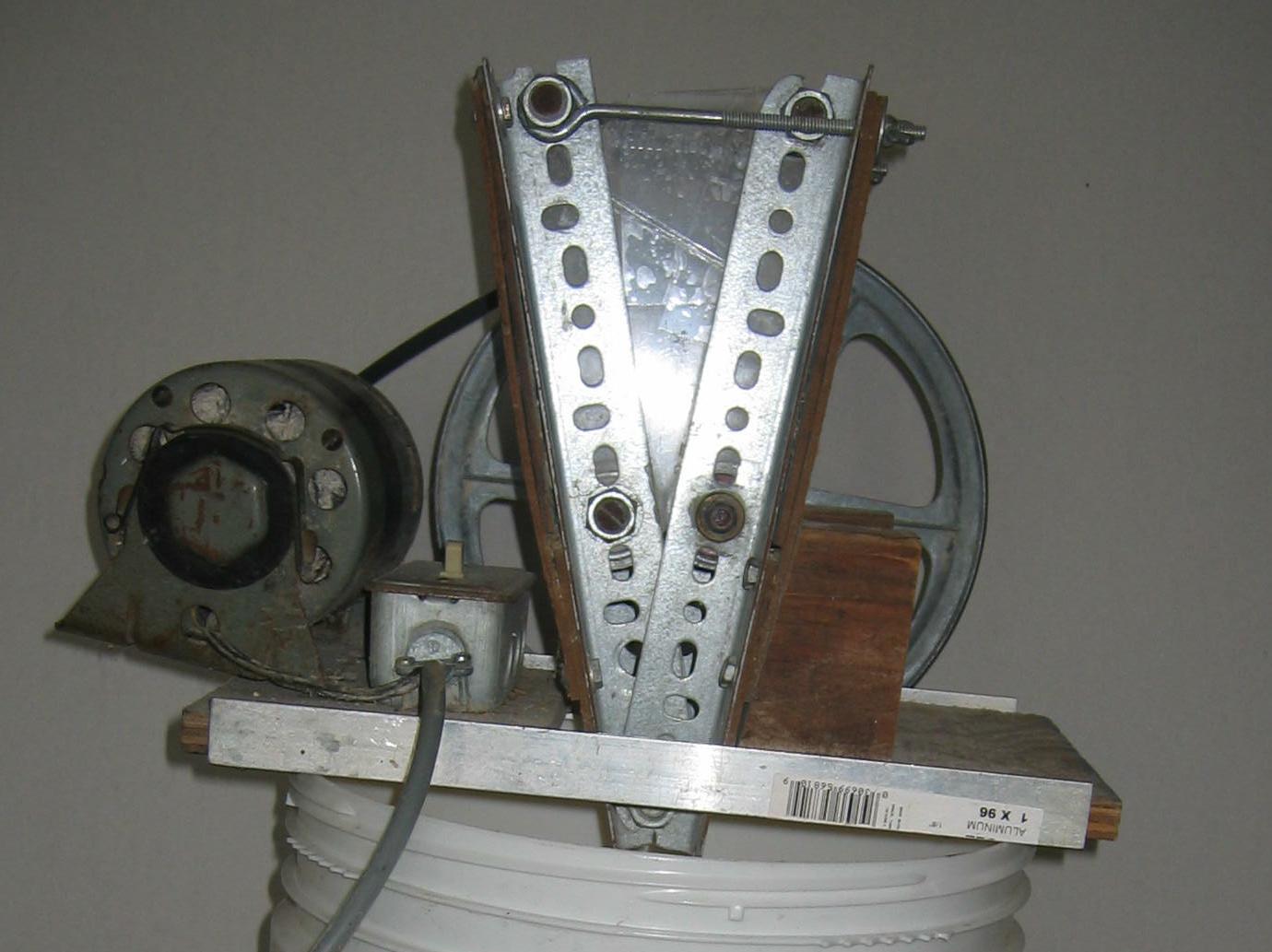
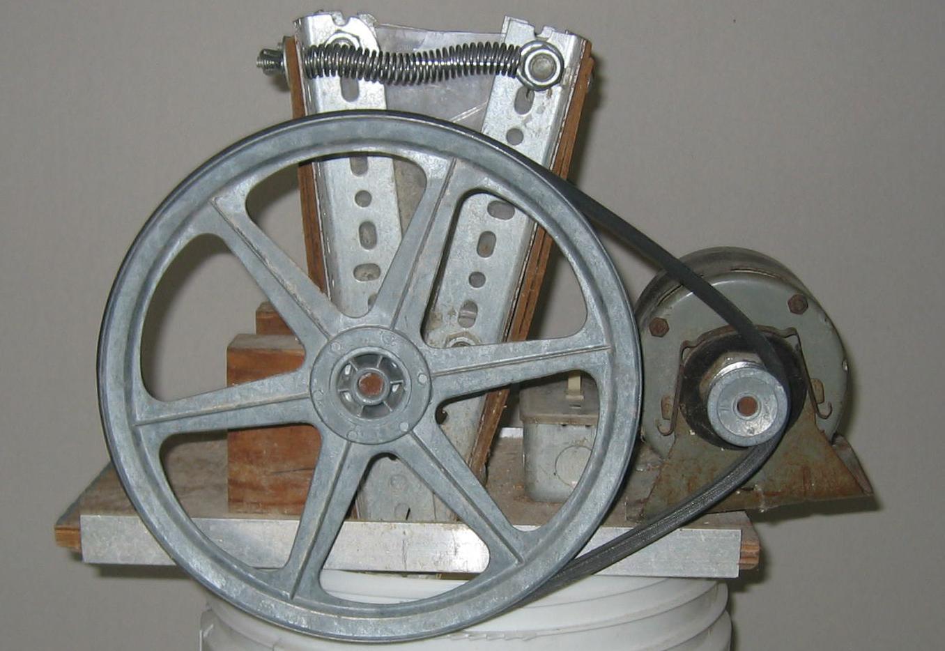
I use the term scissors to describe it because that is the basis for how
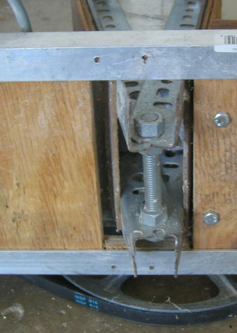
it is assembled and adjusted. There
is one bolt (below the flat plate) that acts as a pivot point as you can see
below.
The spacing between the rollers is controlled by the two thumbscrews at
the top as shown below.
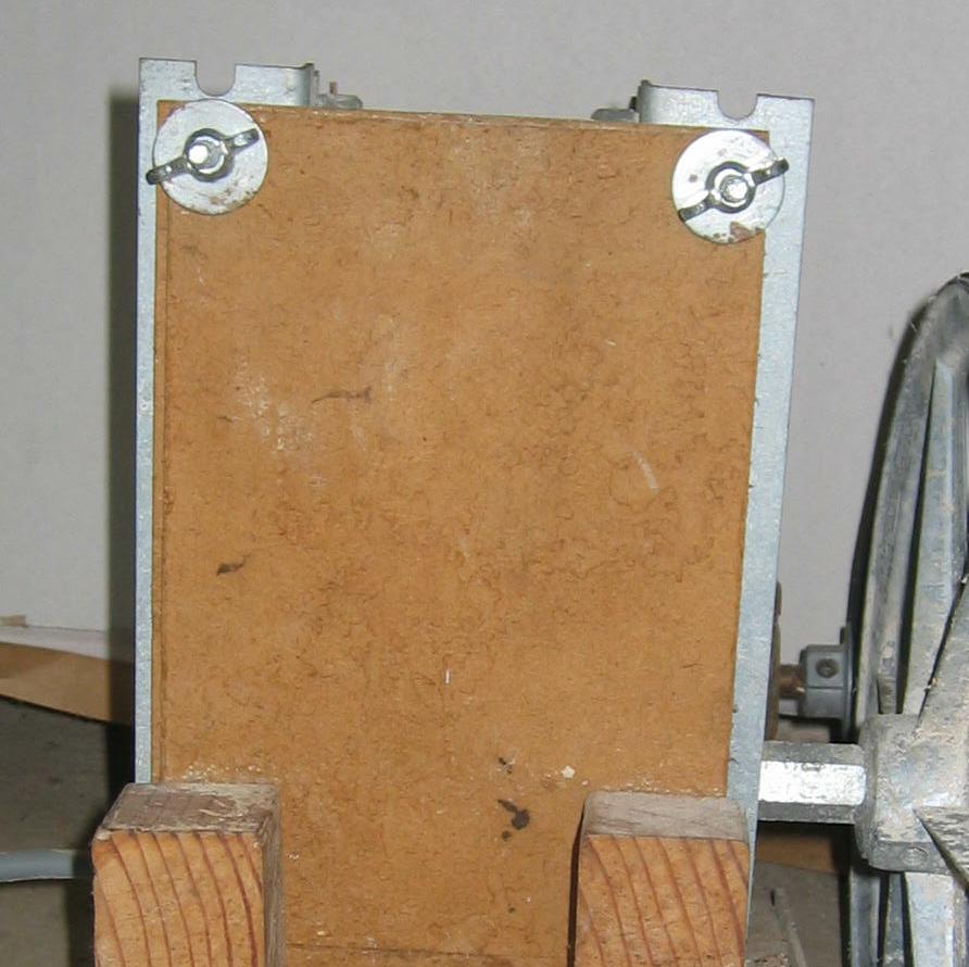
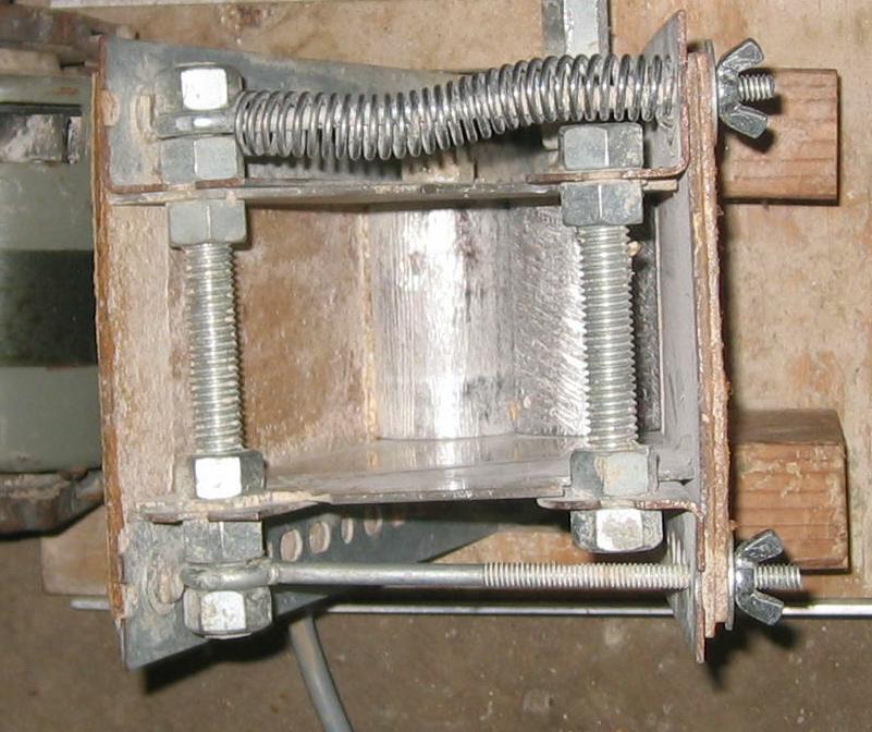
They are screwed on two eyebolts that extend across to the other side
of the frame. One has a spring on
it to keep the frame sides separated. The rollers, eyebolts and spring are
visible in the view below.
The rollers are made from two pieces of galvanized pipe of approximately
1-1/4” ID. The photo below is an example
of the parts.
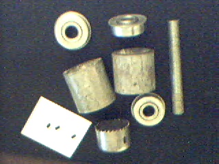
These are not the actual parts that I used. I didn’t want to take the grain mill apart to show them. In the center you can see the two rollers.
The one on the right is the floating roller (as opposed to the one
on the left that is the driven roller). Above and below it are the bearings that keep
it positioned in the frame. The piece
of ½” all-thread at the extreme right functions as the axle for the floating
roller. The bearings just fit in the
pipe and, because they have a lip, they stay positioned at the ends of the
roller.
The floating roller has a similar bearing on one end but, in order to
transfer the turning force to the driven roller, I used a “hole saw”. I happened to have one with buggered teeth
from a previous project. It just fit
inside the pipe/roller. The floating
roller has an axle also made from ½” all-thread but it is firmly attached
to the hole saw which in turn is attached to the floating roller. The three black specks are three setscrews I used to connect the
hole saw to the roller. If you aren’t “lucky enough” to have buggered a hole
saw, you will have to come up with different way to transfer the force from
the shaft to the roller.
I tried a number of different approaches to roughen the surface of the
driven roller. (The floating roller
doesn’t need to be roughened.) In
the end, I decided the best approach was to use a sharp chisel to slightly
“peel” the surface. Rather than hold
the chisel at 90 degrees to the pipe, I tip it to about 45 degrees. Then, just start tapping. If you get a rhythm going, you can ”tap, bounce,
tap bounce, …” right across the pipe.
The frame is made from 4 pieces of perforated angle, each 12” long.
They are bolted together at the scissors point and at the top of each
side. The floating roller axle is
just fitted through the angles on one side of the frame.
For the driven roller, I installed two bronze bushings (bearings) in
the angles forming the other side of the frame. I
had to open up the holes in the angle quite a bit to make these bushings fit.
The pulley on the driven roller shaft is a 10’ pulley. The motor has a 1” pulley. The motor is rated at 1500RPM, 1/10 hp. It usually has enough starting torque however
sometimes I have to just “bump” the large pulley to get it started.
Once started, it has never stalled.
It will crush a pound of grain is seconds.
To adjust it, each side is done separately by adjusting the thumbscrews.
I made a “feeler gauge” out of coat hanger wire.
One end is the thickness needed for crushing barley, the other for
wheat. Since it works so fast, I typically run the
grain through twice; once with a wider setting and then with the “right” setting.
I have compared the results to grain run through a homebrew shop mill
and a brewpub mill and I get similar results.
I have not done a detailed quantitative evaluation of the percentage of grain of various sizes.