Construction Details
In the schematic the colors indicated on various wires are for my reference. They are the color of the conductors of the ribbon cable I used. Obviously they have no bearing on the construction.
The components labeled U3,U4,U5,and U6 are the DS18B20 temperature sensors. I actually mounted them on the end of some stereo headphone cables I picked up at a local Dollar Tree store (for $1.00 each). I just unsoldered the ear phones and soldered on the sensor.
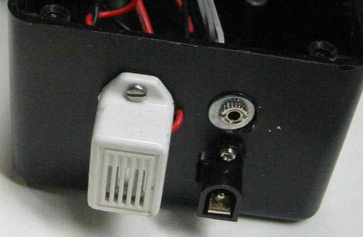
The power connector J1 is a weird connection. The connector I used disconnects the outside contact from the other contact when the plug is inserted. The 5 volt wall wart (A/C adapter) I had applied +5 volts to the center contact and ground to the outside contact. Thus J1 is wired to break the battery ground connection when the plug is installed.
I used two diodes, D1 and D2 to drop the voltage from the 6 volts put out by the batteries down to 4.87 volts (for the diodes I had) for the Vcc supply.
I didn't need R1, the contrast adjustment for the LCD. The contrast seems fine with the line (VCon) disconnected.
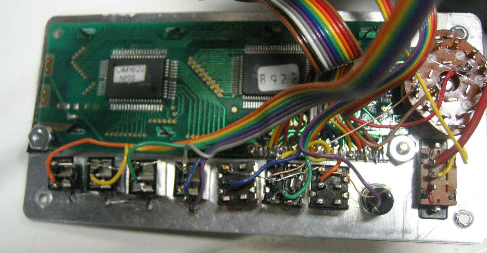
I used an LCD panel purchased surplus from BGMicro. They are only a few bucks and I have had good luck with them. It is a two line unit, 16 characters per line. The unit must come with a controller that is "industry standard". I have found that most if the units have the connections shown, they all seem to work the same. I believe some company like Hitachi came up with a chip that became a standard. Other companies copied the basic elements and added their own bells and whistles. I don't think I used any of the bells and whistles so any controller should work fine.
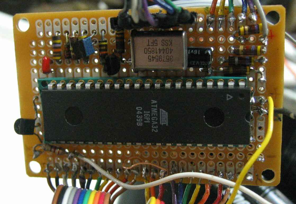
The programmer connection could vary depending on how you program the Atmel chip. I set this up so this circuit provides power to the programmer.
I made the serial interface from discrete components. As I have mentioned elsewhere this circuit was used before and at the time I didn't have a MAX232 handy. This circuit gets the negative voltage needed from the comport of the computer it is connected to. Hey, it works. Initially all the port is used for is to transmit out the temperature readings once per second. Later I plan to upgrade the software to allow remote setup of the alarms.
To connect to this serial circuit, the tip of the stereo plug should be connected to received data (REC) on the computer. The small side contact should be connected to the transmitted data (TXD) on the computer. The grounds are common.
Here are some pictures:
Circuit Board
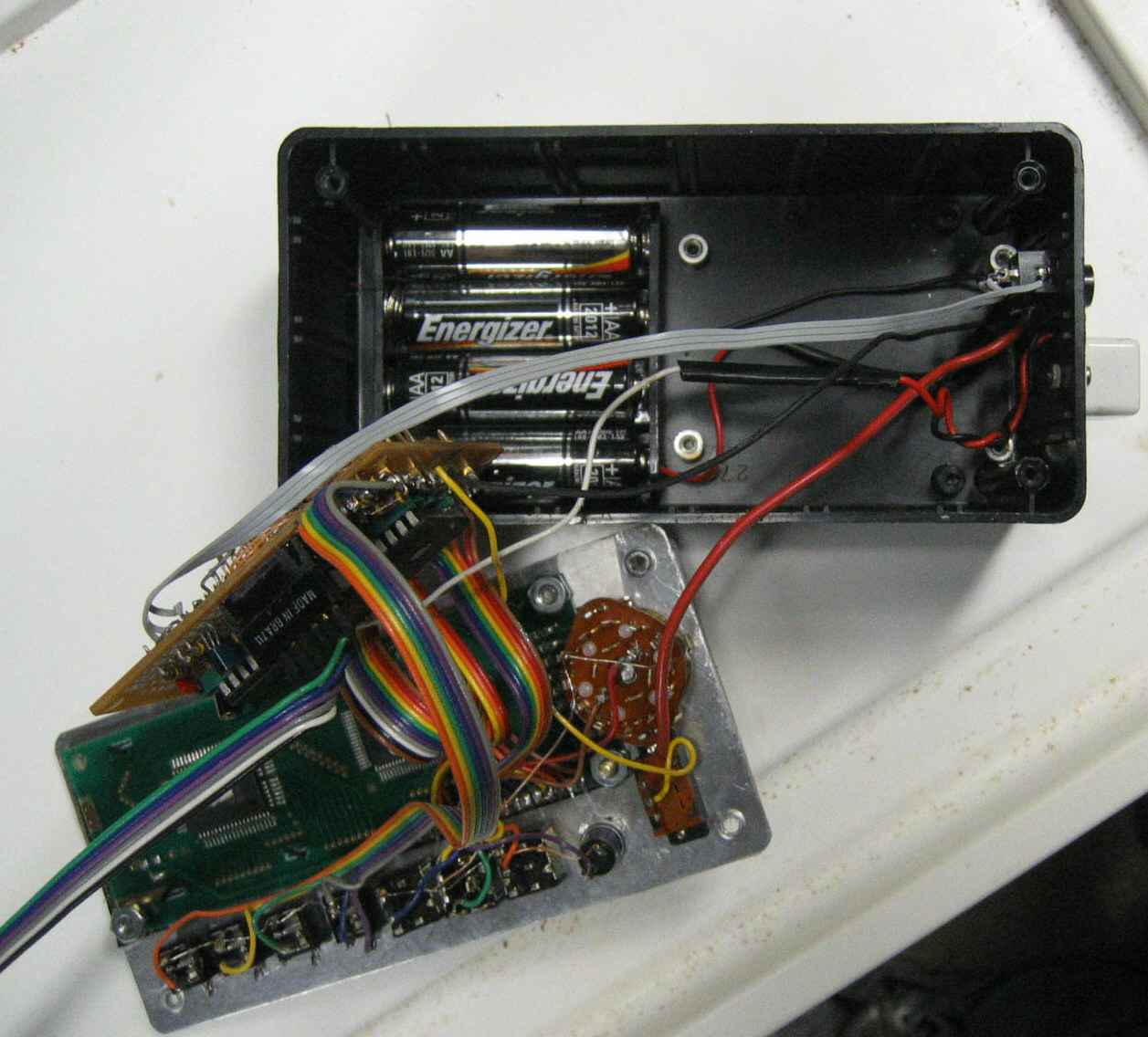
Inside
Rear of Panel
External Connections